“Hear the difference with the highest quality performance cables”
HTP cables are your choice when you want the highest quality at a reasonable price. Professional instrument, microphone, patch and multicore cables are built with high-quality shielded lead and have durable, flexible jackets and rugged NEUTRIK/REAN plugs. For over three decades, legendary Van Damme cables have been the professional's choice for the most demanding cabling applications range as used in Abbey Road studios, BBC, CNN and specified by many of the World's top touring PA hire companies. Whether you're patching up your guitar effects pedals or assembling a complex keyboard rack for your next tour, you need audio cables you can rely on. You can trust our products to get the job done !
All our cables are made to insure the highest sound performance. We manufacture all cables from single leads to multicores using Van Damme cables fitted with top black&golden NEUTRIK/REAN connectors. All cables can be made to client specification including custom cable identification service so we can put cable labels, coloured boots and/or marking rings. We guarantee the highest quality of the products we sell. Several years of successful operation and hundreds of happy customers let us feel certain about that. Besides, all items we sell pass thorough quality control, so no characteristics mismatch can escape the eye of our professionals.
All cables are tested electronicly and as an audio signal connection test before we send them to you. We offer technical support for our products both before and after the sale.
Balanced and Unbalanced Connections (Mike Rivers)
The significance of balanced and unbalanced connections between audio devices, as well as the meaning of the terms, is often misunderstood. A balanced output can be designed, constructed, and connected in many ways, and there are several ways in which balanced and unbalanced devices can be interconnected.Balanced connections have a long history that dates back to the early days of telephony. The phone company runs thousands of miles of unshielded cable between sources and destinations, with very little hum or noise added to our conversations. Yet sometimes it seems we can’t manage to connect two devices in the same rack in our studio without something humming, even if we use hundred-dollar boutique cables. By understanding the right and wrong ways of interconnecting audio devices, you can clean up your studio or sound system.
Myths, Half Truths, and Misconceptions
Thanks largely to the Internet, old stories die hard. To begin our study of making connections, let’s clear up a few misconceptions that have some basis in fact.
- Unbalanced inputs and outputs are high impedance. Nope. Some unbalanced inputs and outputs are indeed high impedance but high impedance connections in modern audio systems are only found in musical instrument pickups and instrument amplifiers. Why ? Because they’ve always been that way.
- Balanced inputs and outputs hum less than unbalanced because they’re low impedance. Partially true. Most balanced outputs are low impedance, but with solid-state equipment, most unbalanced outputs are low impedance as well. When improperly designed or connected, low-impedance connections can hum badly. When properly designed and connected, unbalanced connections can be hum-free. The only high-impedance connections we must deal with today are between electric instrument pickups and amplifiers. It’s true that hum isn’t uncommon here, but it’s because of the design of the pickup, not the connection.
- Balanced connections are “professional”; unbalanced connections are characteristic of consumer or “prosumer” gear. This was close to true in the early days of the project studio but it’s no longer the case. The lines between “pro” and “consumer” are too blurry to make this generalization.
- If you connect a balanced output to an unbalanced input you’ll lose half the level. Sometimes, sometimes not. It depends on the output topology.
The Real Meaning of “Balanced”
“Balanced” isn’t a characteristic of a device; it refers to the connection between two devices or between circuits within a device. Whether a connection between an output and an input is balanced or unbalanced is determined primarily by the source. You can unbalance a balanced source (an output), depending on what you connect it to and how you connect it, but you can’t balance an unbalanced source without adding components. In order for an output to be balanced, the output signal must appear between two terminals, each having the same impedance with respect to a common reference point, which is usually ground. This is an important concept to understand. Contrary to popular belief, it is not necessary for the output-signal voltage to appear on both of the two output lines. Further on, I’ll explain how and why this works. Although the term “balanced input” is common, it’s really a misnomer. To make a proper balanced connection, a balanced output must be connected to a differential input. Half a million engineers aren’t going to quit calling an input “balanced” and start saying “differential” (nor will I) but the term’s significance will become clear shortly.
Balanced vs. Unbalanced Circuits
A device with an unbalanced output produces a voltage between a single “hot” output connection and the circuit’s signal common point, which is usually connected to the equipment’s chassis. The common term for this is “ground,” though it’s not necessarily electrically connected to the dirty brown stuff underneath the house. Similarly, a device with an unbalanced input receives its input voltage between a single “hot” input connection and ground.
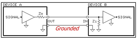
Unbalanced connection with shield grounded.
Usually you can identify an unbalanced device by examining its input and output connectors, though this is getting more difficult with the type of connectors and construction used in modern audio gear. “Mono” ¼” phone jacks and RCA “phono” jacks are inherently unbalanced, since their shield terminal is physically attached to the chassis. For gear built in a plastic box, one jack terminal is nearly always wired internally to the signal ground point. In an unbalanced connection, which almost always is made with a shielded cable, signal current must flow through the cable shield in order to complete the electrical circuit. A good shield can be a pretty effective barrier for electrical noise, but with an unbalanced connection, any noise that gets through the shield or is carried along it will be passed through the chain, just like the desired signal. A balanced output may be described as transformer balanced, electronically balanced, floating, servo balanced, differential, or symmetrical. These are different circuit topologies, all of which provide two output connections with the equal source impedances required for a balanced connection. With certain topologies, the voltage on least one (or sometimes both) of the two signal leads is also referenced to ground, but that’s incidental and not a requirement for a balanced output.
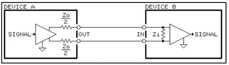
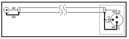
Balanced connection.
A balanced output always consists of two leads, neither of which is connected to the equipment ground. The input of the device receiving the balanced signal sees the voltage between the two signal leads. The cable shield, unlike with an unbalanced connection, carries no signal current (at least, it’s not supposed to). The cable shield is connected to the equipment’s chassis, and it becomes the reference point for any noise voltage picked up by the cable on its way to the next link in the signal chain. On the receiving end, the signal is applied between the two inputs of a differential amplifier or a transformer at the device’s input, rather than between a single point and ground. The output of the differential amplifier, as its name suggests, is the difference between the two inputs. What gives a differential input its advantage is its ability to cancel out common mode noise, that is, noise (unwanted signal, really) that’s identical on both signal leads. Since the difference between the same two numbers is zero, any noise added to both signal leads will be cancelled. This not only includes noise picked up by the wires, but also noise on the ground, since the ground may be common to both inputs. Since we’re concerned with amplifying the difference between two signals, one of them can be zero (at ground potential) all the time, and you’ll still have a difference (signal voltage minus zero) at the output of the differential amplifier. More about this shortly. Remember that what defines a balanced connection is that the source impedance of each of the two output-signal leads referenced to ground must be identical. Here’s how a differential input works in our favor: Let’s focus on the electrical circuit connecting the two devices. Signal current from Device 1 flows through input impedance Zin of the differential amplifier at the input of Device 2. The voltage across Zin is amplified by the differential amplifier. This is the normal desired signal path. This diagram shows Device 1 with what’s known as a symmetrical output configuration. Each lead carries the same signal voltage but with opposite polarity. When one leg of the output is +1 volt referenced to ground, the other is -1 volt. Subtract them in the differential amplifier (remember your high school algebra?) and what you get is double the voltage on either leg measured with reference to ground. But it doesn’t have to be this way, as we’ll see a little later.
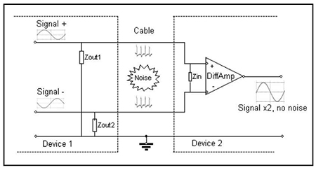
Differential amp cancels noise.
Back to the value of the differential input: When a cable connecting the devices gets too close to a noise source, noise current is induced in both wires (presumably equally since the wires are very close together). This causes the noise current to flow through the two circuit paths. Here’s where the requirement for equal output-source impedances comes into play. Noise current going to the (+) input of the differential amplifier flows through the source impedance Zout1 while the noise current going to the (-) input of the differential amplifier flows through Zout2. Since the currents and impedances are equal, Ohm’s Law tells us that equal noise voltages will be seen at each of the two output terminals of Device A, each one resulting from the noise current flowing through its respective Zout. To a differential amplifier, volts are volts, and the noise is indistinguishable from the desired signal. However, since the noise has the same polarity at both inputs, when the differential amplifier at the input of Device B subtracts the two voltages, the resultant voltage is zero. Presto! The noise is canceled. This, known as common mode rejection, is the advantage of a balanced connection. Typically, XLR or TRS (tip-ring-sleeve) ¼” phone connectors are used for balanced connections, but be aware that while something might look like a balanced connector, the manufacturer didn’t necessarily wire it that way. Some XLRs are wired unbalanced, sometimes with a balancing option available at extra cost, though this is usually only with older (“vintage”) equipment. TRS jacks are commonly used for headphones and channel inserts but these are actually two unbalanced circuits (left/right outputs for headphones and send/return for inserts). Don’t get fooled by looks.
Interconnecting Balanced and Unbalanced Devices
These days, most equipment is designed so that balanced and unbalanced connections in a system can be mixed successfully, but different input and output circuits require different ways of making two wires out of three (or one wire out of two, if you don’t count the shield). Connecting an unbalanced output to a balanced input is straightforward: Simply connect the low (inverting) side of the input to ground. This puts makes one side of the differential always zero volts. Subtracting zero from the signal on the hot input doesn’t affect it in a good or bad way.
Simple unbalanced-to-balanced wiring
This method of wiring between an unbalanced output and a balanced input has everything you need for a complete circuit, and you’ll get a signal to the balanced device. The problem with this method of connection, however, is that it has no common mode rejection. If a cable connecting two devices in this manner (or, for that matter, connecting two unbalanced devices) gets too close to the flashing neon BEER sign in the window of the bar directly behind the stage, you’ll probably have some buzz that you can’t eliminate easily. If your unbalanced output and balanced input are on ¼” jacks, connecting them with a “guitar” (unbalanced) ¼”-to-¼” cable is the electrical equivalent of the aforementioned circuit. The tip of the plug makes contact with the tip terminal of the jack, as usual, while the ring terminal of the jack connects to the sleeve of the plug, which grounds the low side of the input. It’s convenient but still with no common mode rejection.
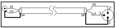
Better unbalanced-to-balanced wiring.
Here’s an alternative and better method of wiring between an unbalanced output and balanced input. By using two-conductor shielded cable, you are at least taking partial advantage of the noise-canceling characteristics of the differential amplifier at the balanced input. Such a connection can provide 20 to 30 dB of common mode rejection—not as good as the 60 dB or more that you’ll get with a balanced source but it’s better than nothing. The disadvantage is that cables wired this way are difficult if not impossible to find off the shelf. Nearly all premade XLR-TS or XLR-RCA cables, and even XLR adapters, are wired with single-conductor cable. For connections like this, you’ll nearly always have to make your own or modify a premade cable but that’s a good skill to develop. Connecting a balanced output to an unbalanced input is a little trickier. You need to know something about the circuit that feeds the balanced output in order to do it properly. Although output connectors can come in various forms, the 3-pin male XLR and ¼” TRS jack are the most common. Conventional wiring, essentially standardized around 11080 when the Europeans and Americans settled on which pin was hot is:
Pin 1 Shield/ground
Pin 2 Signal High (non-inverted)
Pin 3 Signal Low (inverted, or not driven)
TRS jack equivalents are nearly always:
Sleeve Shield/ground
Tip Signal High (non-inverted)
Ring Signal Low (inverted, or not driven)
With that said, beware of vintage equipment, which may be wired with the signal leads reversed !
Balanced Output Circuit Topologies
Throughout the tube era and carrying through the early years of semiconductor design, nearly all balanced outputs employed a transformer. Not only does a good transformer provide a perfectly balanced output, it also isolates the signal leads from ground and, with tube equipment, converts the high voltage and high output impedance of a tube amplifier circuit to a lower impedance and voltage, making it compatible with most inputs. A transformer is the most expensive, and some still consider it the optimum, approach to balancing an output, but even the best transformers add a bit of distortion. High-quality transformers, however, are still found in some of today’s boutique audio devices, primarily for their (desirable) coloration, superior ground isolation, and high noise immunity. A good transformer is the result of sophisticated design engineering and manufacturing, though today, lower quality transformers find their way into audio products primarily as a marketing feature. (“Ours is better than theirs because it has a transformer.”) But with respect to balancing, even poor transformers are pretty good. To unbalance a transformer output, it’s necessary to connect pins 1 and 3 together. Plugging a TS plug into a TRS jack usually will do this automatically. This does no harm to the hardware, the signal quality, or the output level, and the sonic characteristics of the transformer are maintained. The only compromise with this connection is that there’s no common mode noise rejection because by grounding one side of the transformer, the output becomes unbalanced. Note that if you don’t ground the low (pin 3) side of an output transformer, but instead leave it floating, your receiving device will see a very low-level signal that is lacking in low frequencies. This is because there’s nothing but stray capacitance between the transformer windings and ground to complete the circuit. Capacitors are poor electrical conductors at low frequencies, a valuable characteristic when you’re building a filter, but not when what you really want is a piece of wire. Electronically-balanced (or “active-balanced”) outputs come in a several flavors. Each of the two output legs carries an audio signal that’s referenced to ground, identical in voltage but opposite in polarity. When the voltage on pin 2 is +1 volt with respect to pin 1 (ground), the voltage on pin 3 will be -1 volt. If you measure between pins 2 and 3 with a voltmeter, you’ll see 2 volts, and that’s the voltage that a differential input sees.
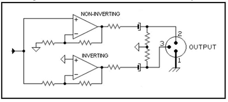
Balanced output with inverting and non-inverting op-amps.
There are two common (read: “cheapest”) circuits used for active-balanced outputs. One adds a unity-gain inverting operational amplifier (op-amp) after the non-inverted output to get the inverted output. In another configuration illustrated here, two op-amps—one configured as a non-inverting amplifier, the other wired in the inverting configuration—are fed the same signal. This is the type of output configuration used for the Main outputs of PreSonus® StudioLive™ mixers. Op-amps sometimes can become “unhappy” when their outputs are shorted, so simply tying pin 3 to ground, while electrically valid, isn’t a good way to connect this type of balanced output to an unbalanced input. It might work fine, but in the worst cases, the shorted-out op-amp could be damaged; the short circuit could be reflected back to the non-inverted output, causing the desired signal to distort; or the grounded output stage could start oscillating, usually at a frequency well above the audible range. The proper way to connect this type of active-balanced output to an unbalanced input is to simply leave pin 3 disconnected. Signal voltage appears between pins 1 and 2, which is just what our unbalanced input wants. This is another instance where you’ll probably need to modify or custom-build a cable if the output is on an XLR connector. If you have this type of balanced output on a TRS jack, you can usually use a TRS-TRS cable to connect it to an unbalanced input. A TS (unbalanced) jack at the input makes no connection to the plug’s ring, which will leave it floating, as we desire. However, some manufacturers thoughtfully use a TRS jack for an unbalanced input, wiring the jack’s ring contact to ground. This assures that you’ll get signal between the unbalanced input and ground when using TRS-TRS cable to make the connection from a balanced output. It works fine for certain types of balanced outputs, like our friend the transformer, but since it grounds the inverted output, it can be a problem for the simple inverting/non-inverting op-amp configuration. It’s from this type of balanced output circuit that the “you lose half your level” factoid originated. Since you’re using only one half of the bipolar (±) output, you’re using only half of the unit’s designed output voltage. If the spec sheet says that the maximum output level is +22 dBu, that’s the voltage measured between pins 2 and 3, or tip and ring. With pin 3 unused you’ll only see half the voltage, or +16 dBu, before the output circuit runs out of steam. Using half of an output can also throw off your metering. It’s fairly common for 0 on a VU meter to represent the nominal output level, typically +4 dBu for a professional balanced output. When the source’s output meter (if it has one) reads 0, the meter on the destination’s input (if it has one) that’s getting only half the total output signal will read -6. The common complaint here is that you can’t get full output from your A/D converters if they’re calibrated for the typical +20 dBu in = 0 dBFS, resulting in half-height squiggles in your DAW waveform display. Another electronically balanced configuration uses what’s often called a “cross-coupled” or “servo” balanced circuit. This generally uses three op-amps and delivers the full voltage between pins 2 and 3, even with one of those outputs connected to ground, the same as when unbalancing a transformer output. This output-circuit configuration was designed to emulate the effect of a transformer, and while it’s far less expensive than a good transformer, it requires a few more parts than a simple op-amp inverter. When connecting this type of output circuit to an unbalanced input, pin 3 should always be grounded. This effectively puts the two legs of the output circuit in series. By grounding pin 3, the full signal voltage, rather than half, will be seen by an unbalanced input connected to pin 2 and ground.
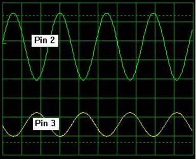
In a cross-coupled output circuit, the difference between the non-inverting and inverting outputs will be correct but the outputs may have different voltages.
In a well-trimmed, cross-coupled output circuit, the outputs will be truly symmetrical— both will be measure the same voltage to ground—but this isn’t an essential requirement. Although the difference between the non-inverting and inverting outputs will always be correct, the outputs may have different voltages, as seen in the scope trace. Leaving pin 3 floating can result in an unpredictable (rather than half the nominal) voltage at pin 2. It can get ugly when nearing the maximum output level: The higher-level output of the two will clip before the lower-level output. Equally nasty is that if the circuit isn’t trimmed for equal output levels, a left-right stereo pair could put a centered source off-center. If you have this type of output, always connect it to a differential (balanced) input or tie pin 3 to ground. One method of creating a balanced output is so simple it seems almost like cheating, and indeed, some condemn it as such. (It’s a popular comment in online forum “reviews.”) But it’s not cheating at all, and it works quite well. The output signal is connected only between pins 1 (ground) and 2. A resistor equal to the output impedance of the op-amp driving pin 2 is connected between pins 1 and 3. This satisfies the balanced output requirement of equal source impedance for pins 2 and 3. How well it works is a function of how accurately the “dummy” impedance on pin 3 matches the active source impedance, but that’s easy to do with inexpensive 1% tolerance resistors, and most manufacturers who use this output configuration do it right.
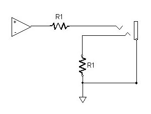
Impedance balanced output.
Since with this configuration the signal voltage on pin 3 is always zero, there’s always a voltage difference between pins 2 and 3 (unless of course the signal voltage is zero), which is just what the differential amplifier at the input of the next device in the chain wants to see. While you’ll occasionally find a balanced XLR output configured this way—it works so well that it’s even used in a couple of pricey microphones—it’s more commonly found on balanced ¼” TRS output jacks. When connecting this type of output to an unbalanced input, grounding pin 3 by inserting an “unbalanced” TS plug into the balanced jack works just fine. Manufacturers like this arrangement because they don’t have to explain everything that you’re reading here to novice users; they can simply write in the manual, “use an unbalanced cable to go to an unbalanced input,” and ensure predictable results. This configuration is often called “impedance balanced” or “single-ended balanced,” although many manufacturers like to describe it as “balanced/unbalanced.” Needless to say, as the simplest and least expensive approach of the lot, it’s popular with manufacturers, particularly with gear most appropriate for personal-studio use. PreSonus StudioLive mixers use this configuration on all of the balanced outputs on ¼” jacks, with exception of the Main ¼” jacks, which duplicate the Main XLR outputs. The DB25 connectors carrying the direct analog outputs are also wired in this manner.
Dual-circuit systems
While unrelated to this balanced/unbalanced discussion, there are a couple of other two-circuit jacks commonly found on audio gear that are worth mentioning. As noted earlier, insert jacks, unless there’s a separate jack for the send and return, are unbalanced. One circuit (typically the tip) is an unbalanced, output and the other is an unbalanced input. Pay attention to these connection guidelines when connecting a processor with balanced inputs and/or outputs to channel inserts. Stereo input and output jacks as commonly found on handheld recorders and players these days are just that – two unbalanced inputs or outputs. Headphone jacks are also unbalanced outputs, generally with a small power amplifier driving them to assure ear-splitting volume with nearly any type of earphone.
Identifying Your Output Configuration
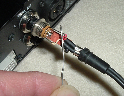
Headphone plug with one lead grounded.
How do you know what type of balanced output you have ? The easiest way is to look at the schematic diagram. Published schematics are a rarity these days but you might get a clue from the product specs, literature, or a block diagram. If the output is transformer balanced, the manufacturer will probably brag about it. If it’s a ¼” jack, and the manual or spec sheet says “balanced/unbalanced,” it’s probably single-ended, balanced with a resistor. You can confirm this by sending a signal to the output in question and plugging a set of headphones into the output jack (easiest, of course, if it’s a ¼” phone jack). If it’s a single-ended balanced output, you’ll hear sound only in one earphone. If you hear sound in both ears, the tip and ring both carry signal. A symmetrical balanced output will sound odd because the signals going to the two earphones are 180° out of phase with respect to each other. It’s a little more complicated to determine whether an active balanced symmetrical output is cross-coupled or uses a single op-amp to get the inverted output. To sort this out, you’ll need to look at or listen to the level on pin 2 while temporarily shorting pin 3 to pin 1. If your headphone plug has a removable cover, you can check this easily by shorting the ring terminal of the plug (the one closest to the cable end) to the sleeve. An unbent paper clip or a small screwdriver works well for this, or you can use a clip lead. If the level increases, you have a cross-coupled output stage. If it doesn’t change, decreases slightly, or distorts, you have a simple inverter in the output stage. For this test, just listen to the left earphone, since conventional headphone wiring is with the tip (pin 2) going to the left ear. Don’t worry about what you hear in the right earphone.
What’s Best ?
Using balanced connections throughout your system is, of course, best. You won’t sacrifice operating level or headroom, and you’ll have the best immunity from outside noise sources like the TV station across the street or the GSM cell phone in your pocket. A balanced connection also offers more options for dealing with grounding and shielding if you have a hum problem, though that’s a topic for another day. In practice, however, you’ll probably have a mixture of balanced and unbalanced outputs and inputs to connect. With the proper understanding of what’s what, you can achieve good results.
![]()
"Your cables experts"